|
|
OSCILLOSCOPES...the basics. During the 1960's automotive workshops were introduced to the oscilloscope to help in the diagnosis of distributor breaker point ignition systems. With the introduction of electronic ignition systems the role of the oscilloscope to diagnose ignition system problems became more important. Distributorless ignition and on-board computer systems has caused a demand for a more sophisticated type of oscilliscope. The introduction of the lab scope function within the oscilloscope is now common place to cater for the increased demand by technicians to solve many problematic aspects found within the sophisticated electronic circuitry of the modern automobile. However, although the increased use of on-board computer systems to control many assemblies of the automobile ( engine, brakes,transmission, and air-conditioning etc ) the modern vehicle still have "basic" problems that they have always had. Within the ignition system the spark plugs still wear, ignition leads still fail, distributor caps/rotors ( where fitted ) require service. Although on-board computers have very capable on-board-diagnostics there are areas where this type of diagnostics cannot address. Many a hour can be can be spent diagnosing the computer system when the problem was a faulty alternator diode or a partially failed ignition lead. The "basics" must be functioning correctly if the computer system is to function correctly. OSCILLOSCOPE DESIGN In simple terms, an oscilloscope is a voltmeter that measures voltage change over a period of time, and this is displayed on a monitor as a wave form. Early oscilloscope design, which is still in widespread use today, uses "analog" oscilloscope technology. A cathode ray tube similar to that used on a television set consisting of two sets of deflector coils, an electron gun and a phosphorous coated screen is used in this type of oscilloscope. The vertical deflection coils move the electron path up and down on the screen in response to voltage input. The horizontal deflector coils create the "sweep" action, moving the electron gun left to right at a controlled speed, or in response to a "trigger" event. The phosphorous coating glows anywhere the electrons strike the surface and continues to glow for a short period of time after the electrons have hit it, which results in the continuous line or pattern being drawn on the screen. Modern day oscilloscopes utilise digital storage scope technology. A digital storage oscilloscope takes samples of input signals at regular intervals and stores these in a computer's memory. The computer then "reconstructs" the wave form on a computer monitor. This type of system allows for more control over the display of wave forms including features like "record" and "playback". The record capability allows for the capture and playback of intermittent instantaneous anomalies which happen too fast for human eye detection. Once a capture has been effected, waveforms may be played back frame by frame to look for intermittent problems. IGNITION PRIMARY CIRCUIT The function of the ignition primary circuit is to deliver current to the coil primary winding, allow collapsing of the coil primary and dissipation of all the excess voltage. A failure within the primary circuit can be the cause of a failure in the ignition secondary. Always perform a thorough check on the ignition primary before condemning any secondary components. Without a correct voltage source and proper switching, the secondary will not function correctly. A typical ignition primary circuit consist of the following components : battery, ignition switch, ballast resistor, loom resistor ( some models ), ignition coil, a sensor to switch the primary on and off ( breaker points, pickup coil, hall effect sensor ), a condenser ( points ignition ), a noise suppressor, and a module which houses a switching transistor ( electronic ignition ), that controls the primary circuit to ground. Battery : The available battery voltage determines the amount of energy in the ignition primary circuit .An undercharged battery lessens the available voltage in the ignition primary which in turn reduces the secondary output. Ignition Switch : Power for the entire ignition system is via the ignition switch.Excessive resistance in the switch could cause a low primary circuit voltage and this in turn affects the efficiency of the entire ignition system. Primary Resistor ( ballast or loom resistor ) : These resistors reduce the current within the primary circuit to prevent breaker point arcing and in some systems to protect other components within the ignition system. Because battery voltage is reduced when the starter is cranking the resistors are usually bypassed when the starter is engaged. Ignition Coil : The ignition coil acts as a transformer. Current flowing through the coil primary windings creates a magnetic field which surround the secondary windings. This occurs when the breaker points ( points ignition ) are "closed" and while the transistor ( electronic ignition ) is "on". When the primary circuit is interrupted ( points "open" or transistor switches "off" ), the magnetic field collapses and a high voltage is induced in the secondary windings. The high voltage is then directed to the correct spark plug by the distributor cap and rotor. Breaker points : Within the distributor is a cam mounted on the distributor shaft. The mechanical points are opened and closed by the rotation of the cam. The time the points are closed is termed "dwell". At this time primary current flows and coil saturation begins .A longer "dwell" creates better coil saturation which results in a higher secondary voltage. Condenser : Used in breaker point ignition systems to prevent arcing across the contact faces as the points open and to dampen the high voltage spike induced in the ignition primary when it collapses. If the contacts were allowed to arc, premature failure of the contacts would occur resulting in poor vehicle performance or a no start condition. Electronic Ignition Primary Components Due to increased demand for better fuel economy and stringent emission standards electronic ignition systems are used. By utilising a better control over higher voltage output for a longer duration these standards are being met. Many electronic ignition systems also adjust timing and vary the dwell according to engine speed and primary source voltage. Components that make up a typical electronic ignition systems include : Ignition module or igniter, armature wheel/magnetic pickup and a hall effect switch. Armature/Magnetic pickup : The armature is fitted to the distributor shaft instead of a cam. The armature has one trigger arm per cylinder. A magnetic sensor, located next to the armature wheel generates a magnetic field. When the point of the trigger arm passes by, a voltage is induced in the pickup which then signals the ignition module to interrupt the current flow to the coil. Hall Effect Switch : The Hall Effect will produce a voltage when the sensor is in a magnetic field. This type of distributor has a fixed permanent magnet and a sensor with a narrow air gap between them. If the shutter ( sometimes a part of the distributor rotor ) is between the sensor and the magnet, the magnetic field is interrupted and zero voltage occurs, signalling the ignition module. As the shutter moves away from the air gap, voltage is again produced. Ignition Module : This is a solid state device that switches the primary current on and off based on the signals from the magnetic pickup. In most applications, the module varies dwell with engine speed and controls ignition timing. Electronic ignition systems have been developed greatly over the years to increase ignition system performance and reliability. Types of systems include : Breaker Triggered Inductive Ignition, Pulse Generator Ignition, Hall Generator Ignition, Capacitor Discharge ignition, Electronic Spark Timing Ignition, Thick Film Intergrated Ignition and the latest innovation is the Distributorless Ignition System.
|
OSCILLOSCOPE PRIMARY IGNITION PATTERNS.
The oscilloscope is an excellent tool to use to diagnose ignition primary
patterns. The following graphical diagrams are representative of normal and
abnormal primary scope patterns.
Note : The primary wave form shown is typical and does not represent all
ignition systems.
Normal Primary Superimposed Pattern for Contact Breaker Ignition System
|
|
Condenser Oscillations : The
dissipating energy from the collapsing magnetic field of the coil is
discharged to the condensor. This energy is stored briefly in the condenser,
then pushes it back to the coil. Each time the condenser gives up the stored
energy, the energy weakens. This repeats until all of the energy is used up. |
|
|
Coil Oscillations : The energy
in the primary winding is decaying due to the collapse of the magnetic field.
These oscillations show the energy dissipating. |
|
|
Points Close : The contact
breaker distributor points close, dwell begins and current flows through the
coil. There should be a sharp, clean 90 degree drop in the wave form at this
point. "Dwell" is the time the points remain closed. |
|
|
Points Open : At this point the
contacts have opened and this causes the magnetic field in the primary to
collapse, inducing a high voltage in the secondary winding. The current flow
has stopped and spark begins. The upward spike is a representation of the
inductive "kick" in the primary winding when the coil current is
interrupted. |
Normal Primary Parade Pattern for Contact Breaker Ignition System
Oscilloscope set at 200 volt scale.
4 cylinder engine with firing order of 1 3 4 2 shown.
OSCILLOSCOPE PRIMARY IGNITION PATTERNS.
primary pattern showing arcing at points open section of pattern.
Point arcing may be caused by :
................................................defective condenser or bad
condenser circuit.
................................................misaligned, pitted, or burnt
points.
................................................too high a charging voltage.
................................................defective ballast resistor.
................................................worn breaker plate assembly.
primary pattern showing condenser oscillation fault
Condenser series resistance appears as reduced oscillations in the condenser
portion of the pattern.
This may be caused by :
.....................................defective condenser.
......................................poor connection at condenser pig tail or
ground clamp.
Condenser leakage, either internal or external, also appears as reduced
oscillations in the condenser pattern.
An intermittently open condenser may appear as varying large to small
oscillations in the condenser part of the primary ignition pattern.
primary pattern showing point misalignment
point bounce is caused by :
.........................................weak point spring.
.........................................dry cam lobe or hardened deposits on
cam lobes.
.........................................pitted or misaligned points.
.........................................loose points.
IGNITION SECONDARY CIRCUIT
The Ignition Secondary Circuit is termed the high voltage circuit. Depending on the manufacturer of the ignition system, this circuit may be required to handle voltages as high as 35,000 volts. Components that make up the secondary circuit are : Secondary coil windings, distributor cap and rotor ( non - Distributorless Ignition System equipped vehicles ), spark plug leads and spark plugs.
SECONDARY IGNITION OPERATION
When the ignition coil primary current is interrupted by points opening (
contact distributor ignition ) or module/transistor ( electronic ignition )
turns off, the magnetic field in the coil collapses and induces a very high
voltage into the secondary coil windings. The available voltage is then
distributed from the coil tower through the coil high tension lead to the
center terminal of the distributor cap
( non DIS equipped vehicles ).The voltage then passes to the distributor rotor
and is in turn directed in appropriate order to each outer terminal of the
distributor cap as the distributor shaft rotates. Each outer terminal has a
high tension lead and each lead is connected to a spark plug. The arranged
order of the terminals and leads determines the firing sequence of the engine.
The spark plugs provide a pre - determined gap within the combustion chamber so
that each time a high voltage is delivered from the distributor, a spark will
occur. If the correct air/fuel ratio is present in the cylinder at the instant
the high voltage bridges the plug gap, ignition and combustion will take place.
Some Distributorless Ignition Systems use only plug leads to direct the high
voltage to the spark plug, while others either mount a coil directly on the
spark plug, or use printed circuits such as the GM Quad 4.
OSCILLOSCOPE SECONDARY IGNITION PATTERNS
The oscilloscope is an excellent tool that provides a convenient way to observe the secondary ignition circuit operation. The secondary wave form supplies information about voltage changes in all phases of an ignition cycle as they occur. Discrepancies in the operation of the secondary ignition components ( high tension leads, spark plugs, distributor cap/rotor etc ) are readily displayed as are mechanical and emission related faults. Recent oscilloscope designs have the ability to capture and store the screen wave forms for future reference when recalled from a saved data storage area. By comparing a known good secondary ignition wave form to a pattern with a possible fault, correct diagnosis of the component failure and diagnosis time is minimized. Recalling both patterns from the data base becomes another tool to use in the diagnosis and engine tuning areas of todays complex automobile.
OSCILLOSCOPE SECONDARY IGNITION PATTERNS.
The oscilloscope is an excellent tool to use to diagnose ignition secondary
patterns. The following graphical diagrams are representative of normal and
abnormal secondary scope patterns.
Note : The secondary wave form shown is typical and does not represent
all ignition systems.
Normal Secondary Superimposed Pattern for Contact Breaker Ignition System
Normal Secondary Superimposed Pattern for Electronic Ignition System
|
|
The Firing Section is
represented by the Spark Line and Firing Line. The Spark Line represents the
time/voltage necessary to maintain the spark. The length of this line is the amount
of time ( in milliseconds ) that the spark plug is firing. The height of the
Spark Line is the voltage ( Burn Voltage ) that is required to maintain the
spark after the initial Firing KV. |
|
|
The pattern section from B to C
is termed the Intermediate Section.This reflects the dissipation of the
remaining energy in the ignition coil after the plug stops firing. The amount
of oscillations is an indication of coil winding and insulation condition. A
shorted winding will show limited oscillations. |
|
|
Section C to D is termed the
Dwell Section. C represents the point "close" ( contact breaker
ignition ) and module "on" |
|
|
Represents the point
"open" ( contact breaker ignition ) and module "off" (
electronic ignition ) systems. |
|
|
Represents the coil current
limiting section of the wave form. |
|
|
Firing KV. This is the voltage
required to start a spark across the plug gap. This voltage is dependent on
several factors including : mixture, compression, plug gap, rotor gap,
ignition timing and resistance of high tension ignition cables. |
Secondary Wave Forms
Summary of Firing KV : This is the voltage required to ionize or initially develop the arc across the spark plug gap.
Variables that raise KV include :
high compression
lean mixture
high resistance in high tension cable
wide rotor gap
worn spark plug
retarded ignition timing
sudden engine loading
Variables that lower KV include:
low compression
rich mixture
small spark plug gap
grounded or fouled spark plug
advanced ignition timing
Summary of Burn Time : This is the measurement of how long the spark is maintained in the combustion chamber when the spark plug fires. Most of the available energy in the ignition coil is used maintaining the spark during this period.
Factors that affect Burn Time include :
coil output
secondary circuit resistance
air/fuel charge quality and flow
secondary short circuits that cause energy to be shunted elsewhere
low primary current ( high primary resistance )
Summary of Burn KV : The KV measurement taken from the center of the spark line. This is the KV required to maintain the spark after the initial Firing KV.
There is a close relationship between Firing KV and Burn KV. If Firing KV is
high, Burn KV will be high and the inverse is true. Higher compression will
result in a high Firing KV and because the high pressure is present for the
duration of the spark, the voltage needed to continue the spark, Burn KV, will
be also proportionately high.
At the moment of coil firing, there is a finite amount of energy that can be
delivered. If the engine variables require a high Firing KV and high Burn KV,
most of the energy will have been used. Consequently, the duration ( or Burn
Time ) of the spark will be short.
If the Firing KV is low and the Burn KV is low, Burn Time will lengthen due to
the longer time required to dissipate the coil energy.
Secondary Wave Forms
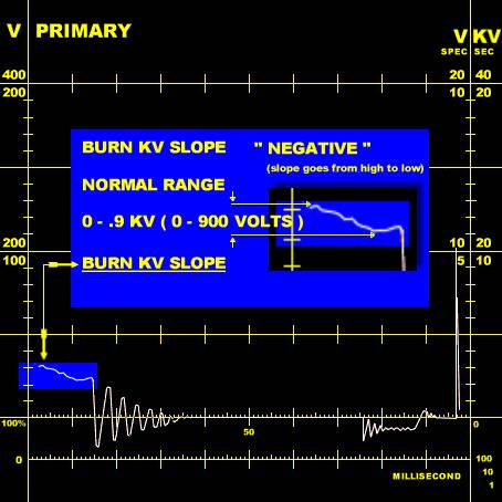
Burn KV Slope
This measurement is the difference in Burn KV from the start of the Spark Line to the end of the Spark Line. The wave form may show a positive slope or a negative slope. If the slope is from high to low it is termed negative slope and if the slope goes from low to high it is termed positive slope.
The ideal Spark/Burn Line would be straight and have a Burn KV of zero.
However, a straight Spark/Burn Line with a low Firing KV could be a fouled
spark plug on some engines.The normal KV measurement should be from 0 to .9 KV
Positive or Negative.
The Burn KV slope and Firing KV can be used to identify whether a problem
exists in the fuel/combustion/mechanical or electrical/ignition systems.
If the slope is Negative and Firing KV is high the problem is usually
electrical/ignition related.
If the slope is Positive and the Firing KV is high the problem is usually fuel,
mechanical, or combustion related.
If the slope is fairly flat with little Positive or Negative slope and the Burn
Time is over 2.5 ms ( milliseconds ) and Firing KV is low, check for a voltage
leak to ground or a possible fouled spark plug.
Spark Plug Firing Voltage
The spark plug firing voltage is the voltage required to overcome
distributor ignition rotor gap and spark plug gaps and to establish a spark
across the spark plug electrodes. The condition of the spark plugs and/or the
secondary circuit, engine temperature, fuel mixture and compression pressures
may affect the required firing voltages.
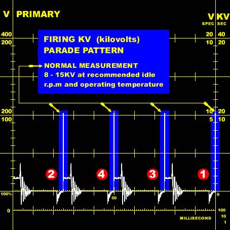
The initial high voltage to ionize or bridge the gap of the spark plug is
called the Firing KV ( Kilovolts ) and can be observed on an oscilloscope by
using the Firing KV Parade function. By observing the Firing KV Parade pattern,
Average KV ( Kilovolts ) and Delta KV ( Kilovolts ) can be measured to
ascertain if problems exist in a particular cylinder, several cylinders or is
common to all cylinders during combustion.
When using the Firing KV Parade pattern in conjunction with measurements from
the Secondary Raster Pattern, confirmation of particular problems are readily
determined.
Average Firing KV Summary.
The normal measurement range ( at the manufacturers recommended engine idle
speed and operating temperature ) is : 8KV to 15KV with no more than 3KV
difference between cylinder to cylinder .
Variables that Raise Average KV :
High compression
Lean Fuel Mixture
Spark Plug Lead Resistance
Wide Rotor Gap
Worn Spark Plug
Retarded Ignition Timing
Variables that Lower Average KV :
Low Compression
Rich Fuel Mixture
Small Plug Gap
Advanced Ignition Timing
Shorted Spark Plug Lead
Delta KV Summary.
The Delta KV is established by expressing the difference between the highest
and lowest Firing KV readings during a set sampling period when using a digital
oscilloscope. The normal measurement range of Delta KV is 2 - 4 KV.
A low Delta KV would indicate that Firing KV's remained stable during the
sampling period ( i.e. fuel mixture, turbulence, plug gap, compression remained
at a constant value ).
A high fluctuation, or high Delta KV, would indicate Firing KV's varied greatly
during the sampling period.
Conditions that would result in high Delta KV readings include :
Lean Mixtures
Intermittently Fouled Spark Plug
Intermittent Compression Loss
Vacuum Leaks
Exhaust Gas Re Circulation
Fuel Injector Spray Pattern
Intermittent Loss of Secondary Voltage
Secondary Ignition Firing KV Pattern
Oscilloscope set to 20KVscale.Wave
form for 1994 Nissan Pulsar GA16 ( DE ) 1597cc engine
with Nissan Electronic Ignition ( firing order 1342 ) shown.
Secondary Ignition Firing KV Variation Pattern
Oscilloscope set to 20KV scale.Wave
form for 1994 Nissan Pulsar GA16 ( DE ) 1597cc engine
with Nissan Electronic Ignition ( firing order 1342 ) shown.
Snap Kilovolts ( Snap KV )
Snap KV measures the voltage required to fire the spark plugs under a loaded
condition. This is accomplished by snapping the accelerator open very quickly.
During this sudden opening of the accelerator, combustion pressure (
compression ) in the combustion chamber rises greatly, fuel mixture momentarily
leans out and ignition timing advances.
Snap KV is therefore a Firing KV reading during acceleration. As the cylinder
pressures are higher, ignition timing is more advanced and the fuel mixture is
leaner during the sudden opening of the throttle, the required voltage to fire
the spark plugs is much higher than that at an idle condition.
The importance of the Snap KV measurement is shown by comparing it to the maximum or total voltage the coil is able to provide. If a coil produces 30 kilovolts maximum voltage and an engine requires 28 kilovolts to fire the spark plugs under a snap throttle condition, a reserve of only 2 kilovolts is left. With this scenario it is probable that the ignition system will fail and an ignition misfire will occur during heavy acceleration uphill.
note : The Snap KV test will not express the same amount of voltage required to fire the spark plugs at 80 kmh, accelerating hard up a hill. Only actual driving conditions can simulate this of required firing voltage, i.e., road testing with special equipment attached to the ignition system or the use of a dynamometer whilst monitoring the oscilloscope readings.
To ensure that a misfire under load is not attributed to demand being more than is able to be provided, Snap KV should be no higher than three quarters ( 3/4 ) of the total coil output. ( i.e., if the maximum coil output is 40 KV, maximum allowable Snap KV would be 30 KV. A reserve voltage, or margin of 10 KV. )
Determining the cause of high Snap KV can be difficult. Under most conditions Snap KV is generally proportional to Average KV. A Cylinder with a high Average KV will tend to produce a higher Snap KV than other cylinders. In general, a high Snap KV is related to spark plug electrode condition. When a spark plug is new, the inner electrode is square, with a sharp edge. As the electrode "wears", it becomes rounded in shape as the electrode erodes during spark discharge. By nature, an electric arc jumps easier from a sharp edge than that of a rounded one. The electrons can concentrate easier at a sharp corner and with a shorter distance to jump, results in the arc being established sooner ( i.e., a lower firing voltage ). The effect of a round electrode on a worn spark plug, with a longer distance to jump, produces a higher Snap KV.
The ignition timing curve also has an effect on Snap KV. Under normal
operating conditions, the spark is established well before the peak cylinder
pressure at high speeds.
for example : envision a spark occurring occurring 28 degrees before top dead
centre at 2500 revolutions per minute.
From the point of ignition, the crankshaft has to move 28 degrees before the
piston reaches top dead centre ( TDC ) and peak compression pressure.
Although the overall cylinder pressure is increased by the acceleration load,
this is offset by firing the spark earlier, well before the peak pressure is
reached. By retarding the timing of the advance curve, the spark occurs closer
to top dead centre or at a point where cylinder pressure is much higher. As a
result, Snap KV becomes much higher.
Another area that makes for difficult Snap KV diagnosing is spark plug " coating" from fuel additives. This coating is usually yellow in colour and at cool idle temperatures, it remains a non conductive solid. Under hard driving or rapid acceleration, the increase in cylinder temperature "melts" the coating momentarily and shorts out the spark plug. As soon as the cylinder temperature returns to normal, the coating solidifies and becomes non conductive. A problem such as this will show up on Snap KV measurement as a very low Snap KV reading ( the same reading you would expect from a fouled spark plug ). Usually a short high speed run is enough to burn the coating off and the plug operation will return to normal.
The fuel system can affect the Snap KV readings by delivering either a rich
or lean air - fuel ratio. Rich air - fuel mixtures lower the voltage
requirement to initialise the spark across the spark plug gap. Lean air - fuel
mixtures raise the voltage requirement at the spark plug gap.
Lack of carburettor accelerator pump circuit, incorrect pump squirt nozzles,
injector pintle fouling and fuel pressures are a few of the areas to pay
attention to when incorrect Snap KV measurements are encountered. Use an
exhaust gas analyser to determine overly rich or lean air - fuel mixture
conditions.
The normal range of Snap KV measurement should be at least a 3 KV increase over Average KV, but not more than a 7 - 8 KV increase. Value should typically not exceed 3/4 of maximum available coil output.
Secondary Ignition Snap KV Pattern
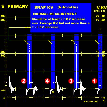
Secondary Ignition Snap KV Pattern
Oscilloscope set to 20 KV scale.
Waveform for 1986 Mitsubushi Cordia AC ( non turbo ) 1755cc 4G37 engine
with Denso Electronic Ignition ( firing order 1342 ) shown
Circuit Gap KV ( Kilovolts )
Circuit Gap KV is the measurement of all gaps in the secondary circuit
EXCLUDING the spark plug gap. Normally the only gap that exists external of the
combustion chamber is the distributor ignition, cap - rotor gap.Depending on
the type of manufacturer's ignition system the voltage utilised to bridge this
gap should be between 3 KV - 8 KV and should not vary greatly between cylinders.
Be aware that there are ignition systems that operate normally at one end of
the good range or the other. Some European systems utilise a resistance within
the distributor rotor and a reading of 6 KV - 8 KV can be expected and some
ignition systems utilise larger rotor air gaps ( as high as .125 inch ) for
ignition noise suppression, again with an expected reading of 5 KV - 8 KV.
Circuit Gap KV is measured under a deceleration condition. During the
deceleration mode the cylinder pressure is lower and a richer fuel mixture is
developed. It is during this period that the spark plug gap is momentarily
below all other gaps and resistances.
A good method to observe Circuit Gap KV is to watch the Firing KV immediately
after performing a Snap KV firing test. When interpreting Circuit Gap KV
readings it is important to note if all the cylinder readings are high or just
a few readings are high.
If all cylinders have high Circuit Gap KV, it is probable that a problem exists in the circuit between the distributor cap and ignition coil.
Possible faults include :
An eroded / broken distributor cap carbon center terminal
A worn rotor ( excessive air gap )
A loose high tension coil lead
A broken high tension coil lead
If the Circuit Gap KV is high for one or just a few cylinders, problem areas include :
Cracked spark plug
An open spark plug resistor
A loose fit of the spark plug high tension lead ( cap/plug insertion )
Distributor cap tower/s corrosion
A broken high tension cable
Secondary Ignition Circuit Gap KV Pattern
Oscilloscope set to 20 KV scale.
Waveform for 1989 Nissan Pathfinder 2389cc Z24 engine
with Denso Electronic Ignition ( twin coil, 8 sparkplug ), ( firing order 1342
) shown
http://www.users.bigpond.com/ergoff/other.htm